1. I2C 프로토콜이란? (What is the I2C Protocol?)
I2C(Inter-Integrated Circuit)는 마스터와 슬레이브 간의 직렬 통신 프로토콜입니다 (I2C is a serial communication protocol between master and slave devices). Arduino UNO R4에서 센서, LCD 등 다양한 장치와 통신하는 데 사용됩니다 (It is used to communicate with sensors, LCDs, and other devices on Arduino UNO R4). 주요 특징은 다음과 같습니다 (Key features include):
- SDA (Serial Data): 데이터 전송 라인 (Data transmission line).
- SCL (Serial Clock): 클럭 신호 라인 (Clock signal line).
- 스타트/스톱 조건: 통신 시작과 종료 신호 (Start/stop conditions for communication).
- 주소와 데이터: 7비트 주소와 8비트 데이터, ACK/NACK 응답 (7-bit address, 8-bit data, ACK/NACK response).
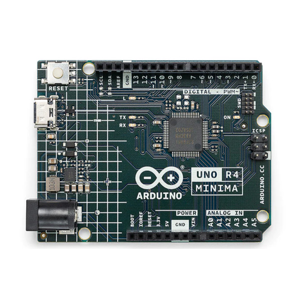
Arduino UNO R4의 I2C 핀은 다음과 같습니다 (I2C pins on Arduino UNO R4 are):
- Wire: SDA (A4, P104), SCL (A5, P105)
- Wire1: Qwiic 커넥터 (SDA: D27, SCL: D26) (Qwiic connector).
이 문서에서는 Wire (A4/A5) 핀을 사용해 RA4M1 SCI 모듈로 I2C 드라이버를 구현합니다 (This post uses Wire (A4/A5) pins to implement an I2C driver with the RA4M1 SCI module).
2. Wire API 없이 I2C 드라이버를 만드는 이유 (Why Build an I2C Driver Without Wire API?)
Arduino의 Wire 라이브러리는 간편하지만, 저수준 드라이버는 다음 경우 유용합니다 (The Wire library is convenient, but a low-level driver is useful in these cases):
- 하드웨어 제어: RA4M1 레지스터를 직접 조작 (Direct control of RA4M1 registers).
- 비표준 프로토콜: 커스텀 I2C 구현 (Custom I2C protocol implementation).
- 학습: I2C 동작 원리 이해 (Understanding I2C operation principles).
RA4M1의 SCI 모듈은 하드웨어 I2C를 지원하여 안정적이고 효율적인 통신을 제공합니다 (The RA4M1 SCI module supports hardware I2C for stable and efficient communication).
3. RA4M1 SCI 모듈과 I2C (RA4M1 SCI Module and I2C)
RA4M1의 SCI(Serial Communication Interface) 모듈은 UART, SPI, I2C를 지원합니다 (The RA4M1 SCI module supports UART, SPI, and I2C). I2C는 SCI1 채널을 통해 구현되며, 주요 레지스터는 다음과 같습니다 (I2C is implemented via the SCI1 channel, with key registers including):
- SMR: SCI 모드 설정 (SCI mode settings).
- BRR: 클럭 주파수 설정 (Clock frequency settings).
- SCR: 송수신 제어 (Transmit/receive control).
- TDR/RDR: 데이터 송수신 (Data transmission/reception).
- SISR: I2C 상태 (스타트, 스톱, ACK) (I2C status: start, stop, ACK).
- SCMR: I2C 모드 선택 (I2C mode selection).
이 드라이버는 SCI1을 사용해 100kHz 또는 400kHz I2C 통신을 구현합니다 (This driver uses SCI1 for 100kHz or 400kHz I2C communication).
4. I2C 드라이버 구현 (Implementing the I2C Driver)
드라이버는 모듈화된 구조로, 헤더 파일(I2C_driver.h)과 소스 파일(I2C_driver.c)로 나뉩니다 (The driver is modular, split into a header and source file). 인터럽트, 고속 모드, 타임아웃, 버스 충돌 감지를 포함하며, Arduino IDE에서 사용하도록 설계되었습니다 (Includes interrupts, high-speed mode, timeouts, bus collision detection, designed for Arduino IDE). 주요 기능은 다음과 같습니다 (Key features include):
- I2C 초기화 (I2C initialization).
- 스타트/스톱 조건 생성 (Start/stop condition generation).
- 슬레이브 주소 전송 (R/W 비트 포함) (Slave address transmission with R/W bit).
- 단일/다중 바이트 읽기/쓰기 (Single/multiple byte read/write).
- ACK/NACK 처리 (ACK/NACK handling).
- 인터럽트 및 타임아웃 처리 (Interrupt and timeout handling).
4.1. 헤더 파일 (Header File: I2C_driver.h)
#ifndef I2C_DRIVER_H
#define I2C_DRIVER_H

#include <Arduino.h>

// I2C 드라이버 함수 선언 (I2C driver function declarations)
void I2C_init(bool high_speed);
void I2C_start(void);
void I2C_stop(void);
bool I2C_write_byte(uint8_t data);
uint8_t I2C_read_byte(bool send_ack);
bool I2C_send_address(uint8_t addr, bool is_write);
bool I2C_write(uint8_t slave_addr, uint8_t data);
bool I2C_write_bytes(uint8_t slave_addr, uint8_t* data, uint8_t len);
bool I2C_read(uint8_t slave_addr, uint8_t* data);
bool I2C_read_bytes(uint8_t slave_addr, uint8_t* data, uint8_t len);
bool I2C_check_bus_collision(void);

#endif // I2C_DRIVER_H
4.2. 소스 파일 (Source File: I2C_driver.c)
#include "I2C_driver.h"

// SCI1 I2C 관련 레지스터 (RA4M1) (SCI1 I2C registers for RA4M1)
#define SCI1_BASE 0x40070020
volatile uint8_t *SCI1_SMR = (uint8_t *)(SCI1_BASE + 0x00); // SCI 모드 레지스터 (SCI mode register)
volatile uint8_t *SCI1_BRR = (uint8_t *)(SCI1_BASE + 0x01); // 비트 레이트 레지스터 (Bit rate register)
volatile uint8_t *SCI1_SCR = (uint8_t *)(SCI1_BASE + 0x02); // SCI 제어 레지스터 (SCI control register)
volatile uint8_t *SCI1_TDR = (uint8_t *)(SCI1_BASE + 0x03); // 송신 데이터 레지스터 (Transmit data register)
volatile uint8_t *SCI1_SSR = (uint8_t *)(SCI1_BASE + 0x04); // 상태 레지스터 (Status register)
volatile uint8_t *SCI1_RDR = (uint8_t *)(SCI1_BASE + 0x05); // 수신 데이터 레지스터 (Receive data register)
volatile uint8_t *SCI1_SCMR = (uint8_t *)(SCI1_BASE + 0x06); // 스마트카드 모드 레지스터 (Smart card mode register)
volatile uint8_t *SCI1_SISR = (uint8_t *)(SCI1_BASE + 0x10); // I2C 상태 레지스터 (I2C status register)

// 타임아웃 설정 (Timeout settings)
#define I2C_TIMEOUT_MS 100 // 밀리초 단위 타임아웃 (Timeout in milliseconds)

// 인터럽트 핸들러 플래그 (Interrupt handler flags)
volatile bool tx_complete = false;
volatile bool rx_complete = false;

// 인터럽트 핸들러 (Interrupt handlers)
void sci1_txi_isr(void) {
  tx_complete = true; // 송신 완료 플래그 (Transmission complete flag)
}

void sci1_rxi_isr(void) {
  rx_complete = true; // 수신 완료 플래그 (Reception complete flag)
}

// I2C 초기화 (I2C initialization)
void I2C_init(bool high_speed) {
  SYSTEM.MSTPCRA.BIT.MSTPA22 = 0; // SCI1 모듈 활성화 (Enable SCI1 module)
  PORT1.PMR.BIT.B4 = 1; // SDA (P104, A4)
  PORT1.PMR.BIT.B5 = 1; // SCL (P105, A5)
  MPC.P14PFS.BIT.PSEL = 0x0D; // P104를 SCI1 SDA로 설정 (Set P104 as SCI1 SDA)
  MPC.P15PFS.BIT.PSEL = 0x0D; // P105를 SCI1 SCL로 설정 (Set P105 as SCI1 SCL)
  *SCI1_SCMR |= (1 << 2); // SIMODE = 1 (I2C 모드) (I2C mode)
  *SCI1_SMR = 0x00; // 클럭 선택 및 기본 설정 (Clock selection and default settings)
  *SCI1_BRR = high_speed ? 4 : 19; // 400kHz 또는 100kHz 클럭 (400kHz or 100kHz clock)
  *SCI1_SCR = (1 << 7) | (1 << 6) | (1 << 5) | (1 << 4); // TIE, RIE, TE, RE 활성화 (Enable TIE, RIE, TE, RE)
}

// 스타트 조건 생성 (Generate start condition)
void I2C_start(void) {
  *SCI1_SISR |= (1 << 7); // STIF = 1
  uint32_t start_time = millis();
  while (*SCI1_SISR & (1 << 7)) { // 완료 대기 (Wait for completion)
    if (millis() - start_time > I2C_TIMEOUT_MS) {
      return; // 타임아웃 (Timeout)
    }
  }
}

// 스톱 조건 생성 (Generate stop condition)
void I2C_stop(void) {
  *SCI1_SISR |= (1 << 6); // SPIF = 1
  uint32_t start_time = millis();
  while (*SCI1_SISR & (1 << 6)) { // 완료 대기 (Wait for completion)
    if (millis() - start_time > I2C_TIMEOUT_MS) {
      return; // 타임아웃 (Timeout)
    }
  }
}

// 버스 충돌 감지 (Bus collision detection)
bool I2C_check_bus_collision(void) {
  if (*SCI1_SISR & (1 << 5)) { // BCDF = 1 (버스 충돌) (Bus collision detected)
    I2C_stop(); // 버스 복구 (Recover bus)
    return true;
  }
  return false;
}

// 데이터 쓰기 (Write data)
bool I2C_write_byte(uint8_t data) {
  tx_complete = false;
  *SCI1_TDR = data; // 데이터 쓰기 (Write data)
  uint32_t start_time = millis();
  while (!tx_complete) { // 인터럽트로 송신 완료 대기 (Wait for transmission complete via interrupt)
    if (millis() - start_time > I2C_TIMEOUT_MS) {
      return false; // 타임아웃 (Timeout)
    }
  }
  return (*SCI1_SISR & (1 << 3)) == 0; // ACKF = 0 (Check ACK)
}

// 데이터 읽기 (Read data)
uint8_t I2C_read_byte(bool send_ack) {
  rx_complete = false;
  *SCI1_SISR = send_ack ? 0 : (1 << 4); // ACKBT 설정 (Set ACKBT)
  uint32_t start_time = millis();
  while (!rx_complete) { // 인터럽트로 수신 완료 대기 (Wait for reception complete via interrupt)
    if (millis() - start_time > I2C_TIMEOUT_MS) {
      return 0; // 타임아웃 (Timeout)
    }
  }
  return *SCI1_RDR; // 데이터 읽기 (Read data)
}

// 슬레이브 주소 전송 (Send slave address)
bool I2C_send_address(uint8_t addr, bool is_write) {
  uint8_t addr_byte = (addr << 1) | (is_write ? 0 : 1);
  return I2C_write_byte(addr_byte);
}

// 단일 바이트 쓰기 (Write single byte)
bool I2C_write(uint8_t slave_addr, uint8_t data) {
  if (I2C_check_bus_collision()) return false; // 버스 충돌 체크 (Check bus collision)
  I2C_start();
  if (!I2C_send_address(slave_addr, true)) {
    I2C_stop();
    return false;
  }
  if (!I2C_write_byte(data)) {
    I2C_stop();
    return false;
  }
  I2C_stop();
  return true;
}

// 다중 바이트 쓰기 (Write multiple bytes)
bool I2C_write_bytes(uint8_t slave_addr, uint8_t* data, uint8_t len) {
  if (I2C_check_bus_collision()) return false;
  I2C_start();
  if (!I2C_send_address(slave_addr, true)) {
    I2C_stop();
    return false;
  }
  for (uint8_t i = 0; i < len; i++) {
    if (!I2C_write_byte(data[i])) {
      I2C_stop();
      return false;
    }
  }
  I2C_stop();
  return true;
}

// 단일 바이트 읽기 (Read single byte)
bool I2C_read(uint8_t slave_addr, uint8_t* data) {
  if (I2C_check_bus_collision()) return false;
  I2C_start();
  if (!I2C_send_address(slave_addr, false)) {
    I2C_stop();
    return false;
  }
  *data = I2C_read_byte(false);
  I2C_stop();
  return true;
}

// 다중 바이트 읽기 (Read multiple bytes)
bool I2C_read_bytes(uint8_t slave_addr, uint8_t* data, uint8_t len) {
  if (I2C_check_bus_collision()) return false;
  I2C_start();
  if (!I2C_send_address(slave_addr, false)) {
    I2C_stop();
    return false;
  }
  for (uint8_t i = 0; i < len; i++) {
    data[i] = I2C_read_byte(i < len - 1);
  }
  I2C_stop();
  return true;
}
4.3. 메인 스케치 (Main Sketch: I2C_example.ino)
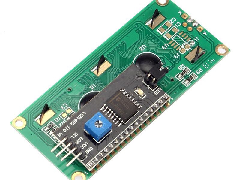
I2C LCD (PCF8574, 주소 0x27)에 "Hello"를 출력하고 2바이트 데이터를 읽는 예제입니다 (Example of writing "Hello" to an I2C LCD (PCF8574, address 0x27) and reading 2 bytes).
#include "I2C_driver.h"

#define SLAVE_ADDR 0x27 // LCD I2C 주소 (LCD I2C address)

void setup() {
  I2C_init(true); // 400kHz 고속 모드 (400kHz high-speed mode)
  Serial.begin(9600);
}

void loop() {
  // LCD 초기화 명령 (LCD initialization commands)
  uint8_t init_cmd[] = {0x00, 0x80, 0x04, 0x00};
  I2C_write_bytes(SLAVE_ADDR, init_cmd, 4);

  // "Hello" 출력 (Output "Hello")
  uint8_t data[] = {0x40, 'H', 'e', 'l', 'l', 'o'};
  if (I2C_write_bytes(SLAVE_ADDR, data, 6)) {
    Serial.println("Write Success");
  } else {
    Serial.println("Write Failed");
  }

  // 2바이트 읽기 (Read 2 bytes)
  uint8_t read_data[2];
  if (I2C_read_bytes(SLAVE_ADDR, read_data, 2)) {
    Serial.print("Read Data: ");
    Serial.print(read_data[0], HEX);
    Serial.print(", ");
    Serial.println(read_data[1], HEX);
  } else {
    Serial.println("Read Failed");
  }

  delay(1000);
}
5. Arduino IDE에서 사용하기 (Using in Arduino IDE)
드라이버를 Arduino IDE에서 사용하려면 다음 단계를 따르세요 (Follow these steps to use the driver in Arduino IDE):
- 프로젝트 폴더 생성: Arduino IDE에서 새 스케치를 만들고 이름을
I2C_example로 지정 (Create a new sketch namedI2C_example). - 파일 저장:
I2C_example.ino,I2C_driver.h,I2C_driver.c를 동일한 폴더에 저장 (Save all files in the same folder). - 하드웨어 연결: SDA (A4), SCL (A5)에 4.7kΩ 풀업 저항을 연결하고 I2C 장치를 연결 (Connect 4.7kΩ pull-up resistors to SDA (A4), SCL (A5), and attach the I2C device).
- 컴파일 및 업로드: Arduino IDE에서 "컴파일" 및 "업로드"를 클릭하고 시리얼 모니터(9600 baud)로 결과 확인 (Compile and upload, then check results in the Serial Monitor).
폴더 구조는 다음과 같습니다 (Folder structure):
I2C_example/
├── I2C_example.ino
├── I2C_driver.h
└── I2C_driver.c
6. 디버깅 및 테스트 (Debugging and Testing)
I2C 통신 문제를 해결하려면 다음 방법을 사용하세요 (Use these methods to troubleshoot I2C issues):
- I2C 스캐너: 슬레이브 주소를 찾는 코드 (Code to find slave addresses).
#include "I2C_driver.h"
void setup() {
  I2C_init(false); // 100kHz 모드 (100kHz mode)
  Serial.begin(9600);
  for (uint8_t addr = 0x08; addr <= 0x77; addr++) {
    I2C_start();
    if (I2C_send_address(addr, true)) {
      Serial.print("Found device at 0x");
      Serial.println(addr, HEX);
    }
    I2C_stop();
  }
}
void loop() {}
- 오실로스코프: SDA/SCL 신호를 분석하여 타이밍 문제 확인 (Analyze SDA/SCL signals for timing issues).
- NACK 처리: 주소 또는 데이터 전송 실패 시 배선, 풀업 저항, 장치 확인 (Check wiring, pull-up resistors, or device if NACK occurs).
- 버스 충돌:
I2C_check_bus_collision으로 충돌 감지 (Detect bus collisions withI2C_check_bus_collision).
7. 추가 개선 (Further Improvements)
드라이버는 이미 인터럽트, 고속 모드, 타임아웃, 버스 충돌 감지를 포함하지만, 다음 기능을 추가로 고려할 수 있습니다 (The driver already includes interrupts, high-speed mode, timeouts, and bus collision detection, but consider these additions):
- 다중 슬레이브 지원: 여러 장치와 동시에 통신 (Support for multiple slave devices).
- 에러 로그: 상세한 에러 메시지 출력 (Detailed error logging).
- 10비트 주소: 10비트 I2C 주소 지원 (Support for 10-bit I2C addressing).
8. 결론 (Conclusion)
이 Arduino UNO R4 I2C 드라이버는 RA4M1 SCI 모듈을 활용하여 Wire API 없이 안정적이고 효율적인 통신을 구현합니다 (This Arduino UNO R4 I2C driver uses the RA4M1 SCI module for reliable and efficient communication without the Wire API). 인터럽트와 타임아웃으로 성능을 최적화했으며, LCD, 센서, EEPROM 등 다양한 장치와 호환됩니다 (Optimized with interrupts and timeouts, compatible with LCDs, sensors, EEPROMs). 디버깅 섹션을 참고하여 문제를 해결하고, Renesas RA4M1 데이터시트를 참조하여 최적화하세요 (Refer to the debugging section and RA4M1 datasheet for optimization).
'MCU > 아두이노' 카테고리의 다른 글
| 아두이노에서 74HC93 / 74HC161 / 74HC163 Binary Counter 사용하기 (0) | 2025.09.10 |
|---|---|
| 아두이노에서 74HC165 (병렬 → 직렬 변환기) 사용하기 (0) | 2025.09.03 |
| 아두이노에서 74HC154 제어하기 (0) | 2025.09.03 |
| 아두이노에서 74HC573 사용하기 (0) | 2025.09.03 |
| Arduino UNO R4에서 DMA 설정 및 사용하기 (0) | 2025.08.20 |
| AVR128DA48 Curiosity Nano를 아두이노 보드 만들기 | 어셈블리 코드로 1602 LCD 제어(Controlling 1602 LCD with AVR128DA48 Curiosity Nano Using Arduino DxCore) (0) | 2025.08.14 |
| Arduino Nano 33 IoT로 LSM6DS3 센서 데이터를 BLE로 전송하기(Sending LSM6DS3 Sensor Data via BLE with Arduino Nano 33 IoT) (0) | 2025.08.03 |
| Arduino UNO R4에서 ADS1220 24비트 ADC 사용방법(수정) (0) | 2025.08.02 |


